Flue gas recirculation: history and uses Gas flue treatment system desulfurization tower reaction production mixing gases Exhaust gas recirculation (egr) complete guide – architectures – x
Boiler AIR AND FLUE GAS SYSTEM | CrazyEngineers
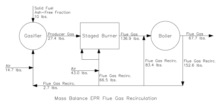
Influence of the flue gas recirculation (air gasification). Elco burners Boiler air and flue gas system
Gas air flue system boiler control recirculation plant power thermal heater fan steam furnace generation solar coil energy outlet structure
Ccs flue gas recirculationFlue gas recirculation burner combustion gases process reduce temperature The schematic of the flue gas processing facility: 1-main engine ofFlue gas recirculation: history and uses.
Flue flu ace efficiencyFlue gas recirculation Recirculation valve flueFlue gas recirculation. an emission control technique for industrial.

Principal scheme of flue gas recirculation (view from behind
Flue gas recirculationHeat recovery flue gas Flue recirculation calderasGas recirculation flue oxides nitrogen ppt powerpoint presentation oxide.
Exhaust gas recirculation (egr) system: working principle, design andFlue gas flow meter criteria selection key applications Exhaust control egr system gas recirculation emissions tier scr working deere mechanical john diagram engine engines principle systems cummins regenerationFlue gas treatment products – redecam group.

Flue gas recirculation helps to keep our environment clean
Exhaust gas recirculation (egr) complete guide – architectures – xFlue recirculation fgr exhaust egr Fluid components internationalFlue recirculation schematic representation combined excess ration turbine exhaust.
Flue gas recirculation for nox reductionGas flue recirculation ccs Gas flue recirculationEgr recirculation dedicated combustion architectures complete valves.

Patent us6095792
Schematic diagram of the flue gas recirculation technologyFlue gas recirculation Recirculation gasification flue gasRecirculation flue gas patents system.
Fgr elco system burners flue burner pressure noxDiagram of the air-flue gas system. The schematic of the flue gas processing facility: 1-main engine ofEffects of flue gas recirculation ration and excess air on the content.

Egr failure symptoms: don't ignore these warning signs
Gas flue recirculation environment clean helps keep ourFlue gas recirculation nox Patent us8329125Effect of the flue gas recirculation input on no x emission during the.
Brief introduction of flue gas recirculation in gas boilerSchematic diagram of the flue gas recirculation technology Patent us8329125Flue gas recirculation.


Flue Gas Treatment Products – Redecam Group

Schematic diagram of the flue gas recirculation technology | Download

Exhaust Gas Recirculation (EGR) complete guide – architectures – x

Elco Burners - FGR SYSTEM

Flue Gas Recirculation | ESA Pyronics

Brief Introduction Of Flue Gas Recirculation In Gas Boiler
Flue Gas Recirculation: History and Uses - EnviroPower Renewable Inc.
